ENEE 206
February 24, 2004
Laboratory 6 - Sequence Analyzers
A. Lab Goals
- The main objective of this lab is to design, build and test a synchronous sequential circuit which detects
a specific sequence from a single-bit input stream.
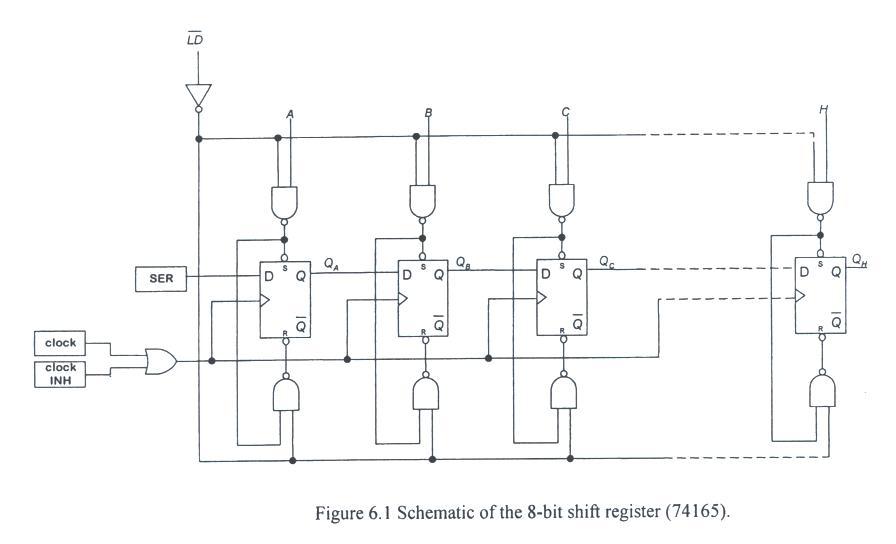
- You will also learn how to use a shift-resister to generate an 8-bit sequence and how to make
the control signals necessay to generate and output the sequence.
B. Background Reading
Read about:
- sequence detectors in section 8.3 of (N/N) or section 6.5 in (M).
- debouncers on p.658 of (N/N) p. 358 in (M). debouncers on p. 658 of (N/N).
- latches and flip-flops in Laboratory 5 of the lab manual.
C. Definitions
- Shift register
- SPDT switch
- Switch debouncer
D. Laboratory Equipment
- No new equipment for this lab.
E. New Hardware
F. Circuit Analysis
- We want to detect a sequence of four consecutive ones.
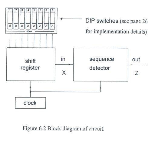
- For every new clock pulse, a new input X appears and a new output Z appears.
- Z will be zero unless the current X and the previous three X's were all ones.
- Overlap will be allowed, so the input X = 101111101 will result in the output Z = 0000011100.
What procedure do we follow to design the sequence detector?
- First, we determine the number of states and draw a state diagram.
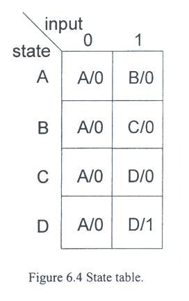
- Then we build the state table and we look to see if any reduction in the number of states is possible.
- Based on the type of flip-flops we use, we make transition tables, simplify the circuitry with K maps, and
finalize the logic and wiring diagrams.
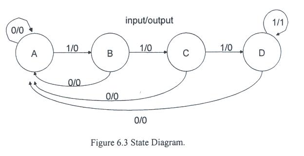
There are four distinct states for our sequence detector, which are labled A - D.
- State A is the state we arrive at any time X = 0, because that means we currently have no consecutive ones.
- The first "1" brings us to state B with zero output.
- The second "1" brings us to state C with zero output, and
- the third consecutive "1" brings up to state D with zero output.
- We should think of states A, B, and C as
having 0, 1, and two consecutive ones(11), respectively, but state D as "three or more consecutive ones."
- Once in state C, if the next input is X = 1, we stay in state D and output a one.
- In any state, if the input is X = 0, we immediately go back to state A and output zero.
State Diagram, State table
See more state diagrams for 1001 and 1011 sequence detectors.
The state table which shows the proper transitions is indicated in Fig. 6.4.
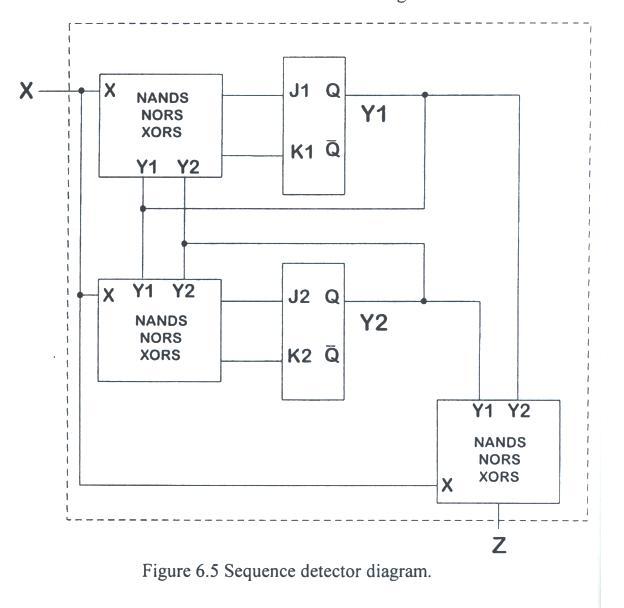
Sequence detector
- An expanded diagram just for the sequence detedtor is shwon in Fig. 6.5.
- We will use J-K flip-flops, because they
have "don't care" conditions on the inputs that could simplify the switching circuit.
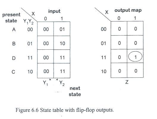
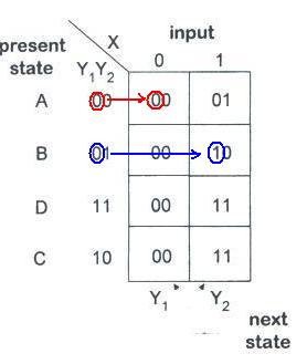
- In Fig. 6.6 we assign the states A - D to specific values of Y1Y2 and rewrite the transition
table in terms of the flip-flop outputs.
- The K-map for the output is given in the right of tge fugure.
- Note that the output is easily expressed as
Z = XY1Y2.
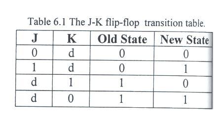
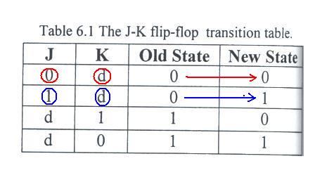
- There are four K-maps required to define the inputs to the flip-flops; they are shown in Fig. 6.7.
- To arrive at these K-maps we made use of the trransition table for J-K flip-flops shown in Table 6.1.
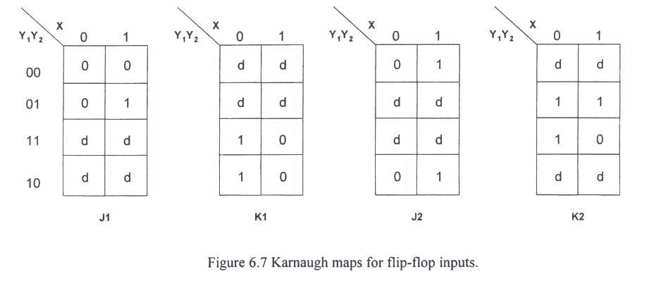
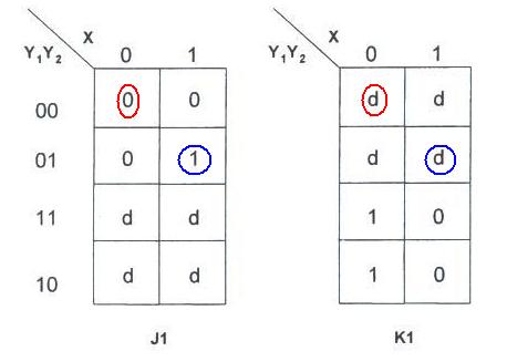
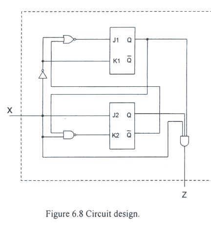
- One possible solution is:
J1 = XY2 = (X' + Y'2)'
K1 = X'
J2 = X
K2 = Y'1 + X' = (XY1)'
- One realization of this circuit is shown in Fig. 6.8.
- The final remaining question is wukk
how to load and run the shift register.
- In previous labs we have used DIP switches and resistors to manually set zeros and ones. That approach will
work just fine for the inputs A - H.
- But control circuitry must be handled differently.
- When loading, we want (LD)' to be low and CLK INH to be high.
- Likewise, the reverse must be true when we are running.
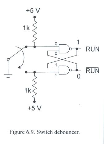
A latch, in the configuration shown in Fig. 6.9 effectively debounces the mechanical switch.
Laboratory 5 Description
Objective:
To build a synchronous sequential circuit with one input and one output which recognizes the sequence "0101" from
an input stream. The circuit must recognize overlapping sequences, so the input x = 10101010 results in the output
z = 00010101 (see Lab 6K in Table 6.2).
Available Hardware:
Digital lcomponent boxes - See Appendix G, SPDT momentary switch
Pre-lab preparation:
Part I - Sequence generation
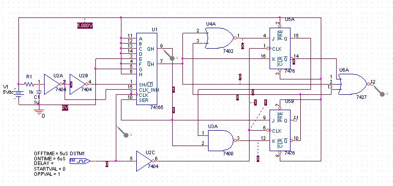
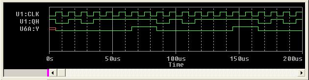
Note that the circuit in Fig. 6.10 is used to simulate RUN button.
The initial test sequence is 10101111 and the analyzer detect a sequence "1111".
Part II - Sequence initialization control
Part III - Sequence detection
Part IV - Alternative design
Experimental Procedure:
During this experiment, be certain that you:
- Ask the TA questions regarding any procedures about which you are uncertain.
- Turn off all power supplies any time that you make any change to the circuit.
- Do NOT apply more that 5 V to the circuit at any time.
- Arrange your circuit components neatly and in a logical order.
- Compare your breadboards carefully with your circuit diagrams before applying power to the circuit.
- Complete the following tasks:
- Part I - Run signal
- Part II - Sequence generation
- Part III - Sequence detection - oscilloscope
- Part IV - Sequence detection - DLA
Part V - Alternative design
Post-lab analysis:
Generate a lab report following the sample report available in Appendix A. Mention any difficulties encountered during
the lab. Describe any results that were unexpected and try to accoundt for the origin of these results(i.e. explain
what happened). In ADDITION, answer the following questions:
- Part I - Run signal
- Part II - Sequence generation
- Part III - Sequence detection
Part V - Alternative design