Parametric Analysis
Simulation of the a Half-wave Rectifier
- In Capture CIS, create a new project hw-rectifier.opj.
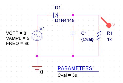
- Draw a schematic of a half-wave rectifier as shown below.
The parts used are VSIN/SOURCE for V1, 0/SOURCE for ground, D1N4148 fot diode, C for C1, and R for R1.
PARAMETERS will be added later.
- Doubl-click the value of (1n) of part C1 to display the Display Properties dialog box.
- In the Value text box, replace 1n with {Cval} (with curly braces) then click OK.
- Repeat the same for the properties of V1 setting the values VOFF=0, VAMPL=5, and FREQ=60.
To add a PARAM part to declare the parameter Cval
- From Capture's Place menu, choose Part (or Shift + p).
- In the Part text box, type PARAM, then click OK.
- Place one PARAM part in any open area on the schematic page.
- Double-click the PARAM part to display the Parts spreadsheet, then click New Column....
- In the Property Name text box, enter Cval (no curly braces), then click OK.
This creates a new property for the PARAM part, as shown by the new column labeled Cval in
the spreadsheet.
- Click in the cell below the Cval column and enter 0 as the initial value of the parameteric
sweep.
- While this cell is still selected, click Display.
- In the Display Format frame, select Name and Value, then click OK.
- Close the Parts spreadsheet.
- From the File menu, choose Save to save the disign.
To set up and run a parametric analysis to step the value of C1 using Cval
- From Capture's PSpice menu, choose New Simulation Profile.
The New Simujlation dialog box appears.
- In the Name text box, type Parametric.
- From the Inherit From list, select AC Sweep, then click Create.
The Simulation Setting dialog box appears.
- Click the Analysis tab.
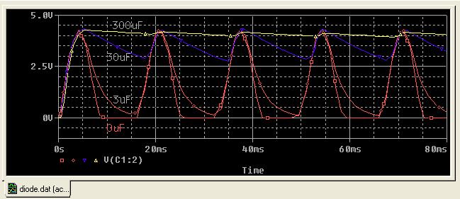
- Under Options, select Parametric Sweep and enter the settings as shown below.
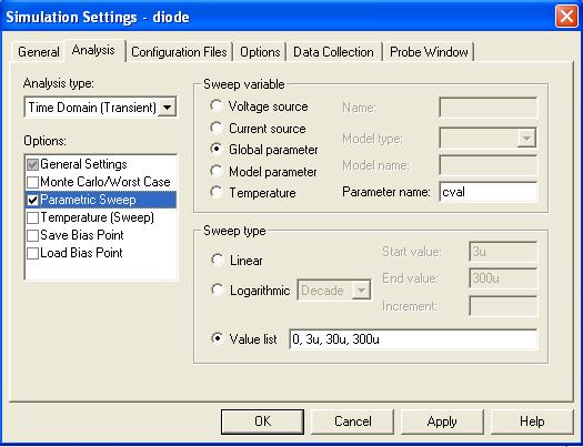
- Click OK.
- From the PSpice menu, choose Run to start the analysis.